Q-CAP / V-CAP mounting recommendations
Q-CAP/V-CAP 04 was designed to further increase the flexibility of C-CAP series and enable conduction cooling.
Q-CAP/V-CAP 04 has an excellent price/kVAr ratio. Q-CAP/V-CAP 04 is protected by US Patent 9799454.
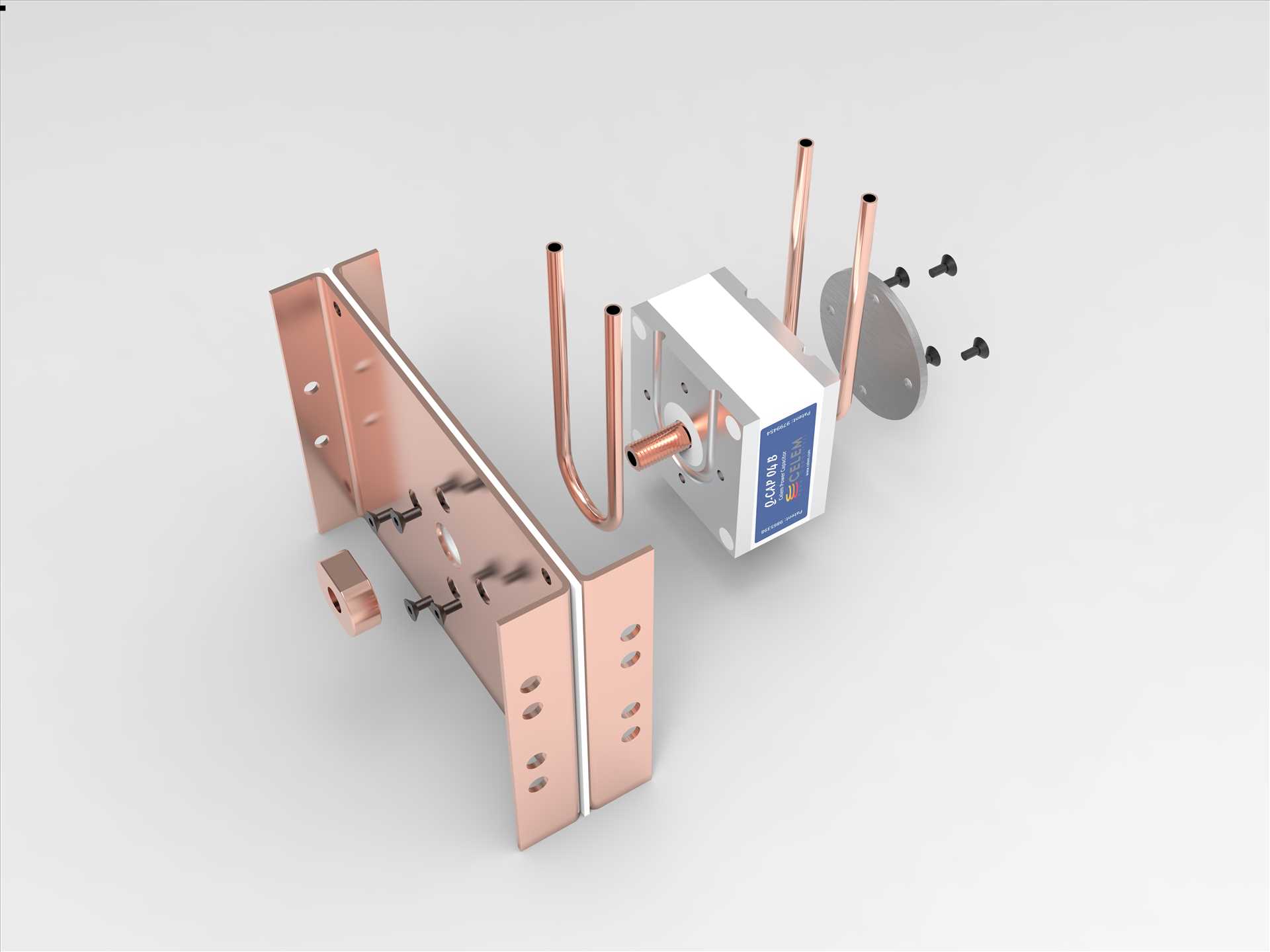
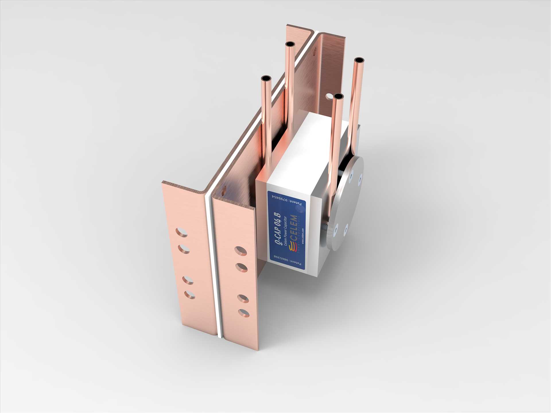
Like the C-CAP, Q-CAP/V-CAP is designed to be connected unilaterally on two busbars separated by an insulation such that the magnetic field is confined between the busbars and the Q-CAP/V-CAPs are not affected by it.
The busbars and insulation should be sandwiched tightly by insulated fasteners.
Busbars must be flat and fully aligned prior to mounting of the Q-CAP/V-CAPs. The Q-CAP/V-CAPs must not be used to align, straighten, compress, or support the busbar.
Busbars should be made with at least 3 mm copper and at least 3 mm Teflon insulation.
Holes in the busbars (see illustration at the bottom of this document)
Holes in the bottom busbar (which is in contact with the upper face of the Q-CAP/V-CAP):
For the central rod of the Q-CAP/V-CAPs 25 mm holes to enable free contactless passage.
For the M6 mounting screws, 6.5 mm holes with a 12.5 mm 90° chamfer.
Avoid using M6 screws which are too long, as they might penetrate the top electrode and damage the bobbin.
Holes in the top busbar:
For the central rod of the Q-CAP/V-CAPs 18 mm holes.
For the M6 mounting screws 16 mm holes to enable free contactless passage.
Holes in the insulation can be as small as possible to increase creepage distance.
Busbar cooling
Busbars should be kept at a temperature cooler than the capacitors to avoid heating of the capacitors by the busbars. In case of high current flowing in the busbar, the capacitors’ cooling is insufficient to cool the busbars and busbars should be cooled separately.
Q-CAP/V-CAP mounting
1.
Mechanical mounting to the bottom busbar using 4 x M6 countersunk screws at 10Nm, ensuring good thermal contact with thermal conductive material (thermal paste or thick silicone oil). Care must be taken about the length of the screws. Screws which are too long will dent/penetrate the thin electrode and damage the underlying bobbin. Please consider the mechanical sketch of the capacitor for screw length choice.
2.
Electrical connection of the Q-CAP/V-CAP is done via tightening the M16 nut onto the top busbar at 15-20 Nm, ensuring flatness and good contact of the nut with the busbar. It is recommended to verify good contact with a gauge.
Q-CAP/V-CAP cooling
Q-CAP/V-CAP should be cooled on both sides of the capacitor.
Q-CAP/V-CAP has a groove on each copper electrode to accommodate a 8 mm OD U-shaped copper tube.
The top copper tube is pressed against the busbar using the force of the M16 and M6 screws of the top electrode.
The bottom copper tube is pressed against the bottom electrode using a flat conductive/nonconductive washer using 4 M6 screws.

Losses should be considered as 1/1000-1/700 of the reactive power. 1000-Watt loss would increase the temperature of 1 liter of water by 14°C at a flow rate of 1 L/min. Outlet water temperature must not exceed 40°C.
The (external) surface temperature of the Q-CAP/V-CAP must not exceed 55°C.
In cases where water is connected in series and high voltage is used, equipotential electrodes should be connected in series to avoid voltage buildup.
The central rod of Q-CAP/V-CAP is hollow with G1/8 thread on each side to enable cooling of the central rod.
Cooling the central rod of Q-CAP enables increasing of the power to 1000 kVAr.
First operation
Prior to the first operation it is recommended to check the tightness of the screws and nuts.
During the first minutes of operation all capacitors should be inspected using an IR camera for validation of adequate water cooling and absence of hotspots.